Before starting the assembly process, ensure that you have removed all protective films from the acrylic pieces. Note that there are protective films on both sides of the pieces. Failing to remove these films may impact the assembly process.
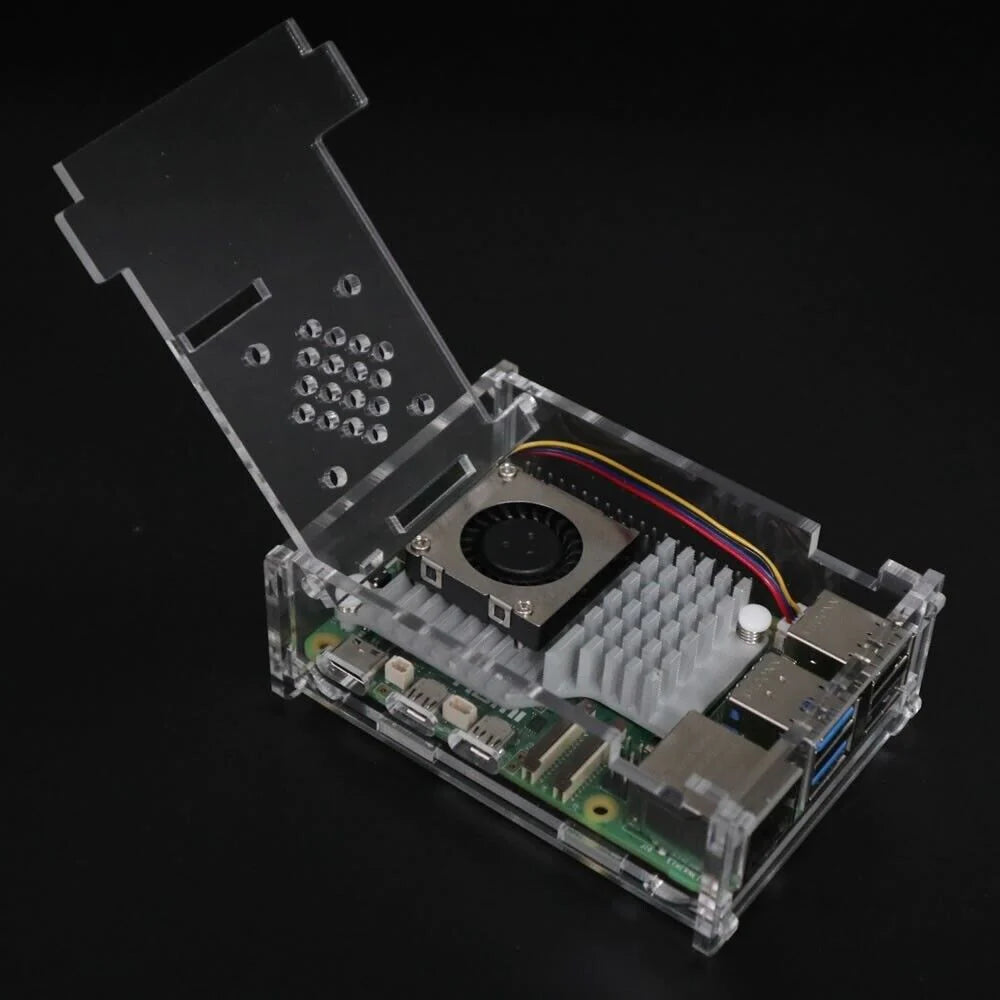
- Install Raspberry Pi 5 active cooler:
- Carefully peel off any protective film from the heat sink if it's present.

- Place the active cooler on top of the Raspberry Pi 5's CPU. Align the screw holes on the cooler with the mounting holes on the Raspberry Pi 5 board.

- Secure the active cooler in place by gently pressing down on the screws and fastening them onto the mounting holes. Ensure that the cooler is firmly attached but avoid over-tightening the screws, as this could damage the Raspberry Pi 5 board.
- Assemble the case:
- Begin by placing the base plate on top of the Raspberry Pi 5 board. Make sure to align the memory chip and TF card slot correctly.

- Next, position the HDMI side plate by slotting it into the tabs on the bottom plate. Ensure that the mini USB port, two mini HDMI ports, and audio port align with the corresponding holes on the side plate.

- Slot the second side plate into the tabs on the bottom plate. Ensure that the round holes on both side plates are at the same height.


- Assemble the USB plate by sliding the top of the USB plate over the two top hooks first. Then, using very light pressure, pivot the USB plate downward over the bottom two hooks. Gently press the bottom two hooks and slide the USB plate into place. If you encounter any severe resistance, stop immediately. Do not force this piece, or you risk breaking the plastic. Instead, back off, check the alignment of the other pieces (especially the HDMI side), and try again gently.


- Install the top plate by inserting its two tabs into the holes on the two side plates. Ensure that the cutout on the top plate aligns with the GPIO ports.

- Similarly, install the TF card plate using the same technique, sliding it from top to bottom.

- Finally, check the lid to ensure it can be opened and closed freely. Verify that the GPIO cutout is aligned correctly and that all the round feet are facing downward.
